
Chromatic Composer
1. Project overview
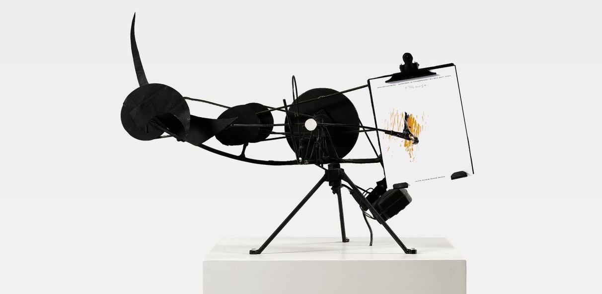
Chromatic Composer (CC) is an interactive drawing and playing machine that acts with sound and visual by translating one into another. It is a friendly robot with a chromatic language; the sound captured with a microphone activates and drives the coloured pens motion into unique creations. Audience can clap, talk, sing or even play a song for CC; more versatile sounds will lead to richer drawings.
“To understand is to perceive patterns.” — Isaiah Berlin
Once the drawing is ready CC functions as an instrument while the drawing becomes a score; users can direct the camera over the drawing and hear the machine’s version.
The process of an analogue sound digitally processed, converted into an “analogue” drawing, and the further iteration of the translation process to complete the cycle back to sound pretends to be an example of the possibilities, advantages and disadvantages that can exist in our connections with technologies.

2. Project development
a) Concept development
Chromatic Composer started with Susana and Olive having the similar interest of exploring mark making practices which interacts with sound elements. The initial idea was building a machine that translates sounds into drawing which could be read and produce sounds again. This is the conceptual idea of our projects that according to which we have built three prototypes.
However, building a machine that produce standard patterns is not where we are going since numerous practices have been working on exactly marking the audio by drawing or visual elements and reproduce it into the same sounds as input. What we have been deeply considering and focusing on is how the machine would specify the form of input and output in a more stimulating way for users to interact with. Storyboards, low-fidelity prototype and flowcharts were used for immersion design, and a wide research on related topics is always inspiring. The technical limitation of implementation was not considered at this stage but it’s still practical to pay attention to the methods and techniques used in the precedents when doing research.

Data and interaction flowcharts

Low fidelity prototype
Here are the blog posts that related to this process:
Design Ideation
http://prezi.com/zouhjh_mo3wx/chromatic-composer/
Sketching
https://idea9202studio.wordpress.com/2013/09/13/sketching/
b) Iteration Design & Prototyping
As an interactive installation we target the user group of Chromatic Composer to be any people, so instead of doing statistical user analysis on user’s cognition and expectation of a sound <–> visual machine, we are more interested in the artistic and unexpected expression made possible by a machine of which the behavior is not completely pre-defined. So during the implementation we have placed ourselves in the user point of view to interact with the equipment while taking in feedback from our tutors and classmates. And we trust our judgment as designers in assessing what we have experienced.
After the low-fidelity prototype at the ideation stage, we have built two high-fidelity prototypes, successfully connected and communicated the two Arduino boards with processing and G-code run on the computer, and then controls the movement of the x,y plotter and the servos. We ran a virtual interface on the computer to test the painting before getting the plotter done.
Step by step we solved problems like constraining the drawing extent, providing sufficient power for servos, controlling three of them at the same time through Arduino serial, and adjusting the small angular movement. Later we explored the possible styles of painting, introducing curve strokes to produce more compelling drawings, and tried to experiment how the machine reacts to different types of music. We found it interesting that the machine could be ‘self-learning’ which means that it would listen to its own sounds and produce drawing and vice versa. It’s also amusing that when it listened to other machines or talking in the studio it followed and responded by moving and making noise itself, which is like an ongoing dialogue.
For the reading part, colours on the paper were mapped into a range of frequencies that result in several instruments in SuperCollider which communicates massages with Processing code. We also tuned the audio output to make the instruments sound clearer and more significant for changes corresponding to the reading from the camera. We discussed two different ways that user could interact with in the reading process: to handle the drawing paper on a piece of glass over the camera, or to hold the camera and scan the drawing while moving it above the paper.
Though the alpha version works fine, we still decided to build a beta prototype using 4.5mm plastic boards and laser cutting in order to improve the unstable movement caused by imprecise measurement and cutting, and certainly to make the machine look better. Before cutting the boards, we re-measured the sizes and the positions of every hole that used to fit in the motors, screws and other components. Some metal components of the alpha version would be kept for the beta one, like the wheels and metal carriers installed beneath the y-axis bridge. Problems like balancing the car on y-axis, hiding the wires and boards in boxes are also considered when designing the new prototype.

So when the beta version was done, we fixed the unstable movement of the y-axis bridge and turned the tip of the pens into soft brushes, which terminated the swinging and dancing of the pens when stuck during the drawing, leading to smooth straight lines and coherent curves and much better interactive experience.


As for exhibition condition, challenges could be drying brushes requiring water supply, noisier environment that result in less timely interaction or anything else that we . But the most exciting thing would always be the uncertainty of drawing and reading, where we really hope the users would be having great fun to play with.
Here are the blog posts that related to this process:
CHROMATIC COMPOSER – AUDIO INPUT
https://idea9202studio.wordpress.com/2013/10/10/chromatic-composer-audio-input/
CHROMATIC COMPOSER – READ THE DRAWING
https://idea9202studio.wordpress.com/2013/10/23/chromatic-composer-code-draw/
CHROMATIC COMPOSER – PLOTTER PROTOTYPING
https://idea9202studio.wordpress.com/2013/11/02/chromatic-composer-prototyping/
CHROMATIC COMPOSER – HOLDING PENS
https://idea9202studio.wordpress.com/2013/11/04/chromatic-composer-holding-pens/
CHROMATIC COMPOSER- MAKING THE DRAWING
https://idea9202studio.wordpress.com/2013/11/11/chromatic-composer-making-the-draw/
CHROMATIC COMPOSER- FINAL PROTOTYPE
https://idea9202studio.wordpress.com/2013/11/15/chromatic-composer-final-prototype/
Appendix
1. Video documentation
CHROMATIC COMPOSER- VIDEO
https://idea9202studio.wordpress.com/2013/11/15/chromatic-composer-the-end-and-video/
2. Schedule
|
Phase 1: Grounding research and ideation |
||
| WEEK 6 | 2 Sep – 3 Sep | Collect:- Example of a mark-making practice
– Art/design/technology precedents – Inspirational material |
| 4 Sep – 5 Sep | Collect:- Journal article
– research paper – Books |
|
| 6 Sep | – Presentation: individual findings- Found a group | |
|
Phase 2: Concept proposal |
||
| WEEK 7 | 9 Sep – 10 Sep | – Decide on a single concept in a group |
| 11 Sep – 12 Sep | – Sketching- Storyboard
– Building low-fidelity prototyping |
|
| 13 Sep | – Presentation: group ideation | |
|
Phase 3: Prototyping and evaluation |
||
| WEEK 8 | 16 Sep – 22 Sep | – Programming testing:Processing, Minim, PureData, SuperCollidar
– Specification: drawing and reading processes |
| WEEK 9 | 23 Sep – 29 Sep | |
| WEEK 10 | 30 Sep – 6 Oct | – Mid-term break |
| WEEK 11 | 7 Oct – 13 Oct | – Presentation: audio input, desktop user interface |
|
Phase 4: Final documentation |
||
| WEEK 12 | 14 Oct – 20 Oct | – Building high-fidelity prototypes- Testing motors and circuit board |
| WEEK 13 | 21 Oct – 27 Oct | – Building high-fidelity prototypes |
| 25 Oct | – Presentation: working prototype | |
| WEEK 14 | 28 Oct – 3 Nov | – Building high-fidelity prototypes |
| WEEK 15 | 4 Nov – 10 Nov | – Exploring different ways of drawing- Improving audio output |
| WEEK 16 | 11 Nov – 15 Nov | – Building beta prototype with laser-cut plastic board- Photos & videos
– Documentation |
